Skip to main content Skip to footer
Home
User manuals

Main navigation

  • Home
  • Enterprise for Engineers
    • Program overview
      • Getting started
      • Product browser
      • Recent activity
      • Viewer tab
        • Product viewer
      • Specifications tab
        • Product Specifications viewer
        • Product documentation
        • Product buildup viewer
        • PCBA Components
        • Product sharing
      • Quotation
      • History
      • Shopping Cart
    • File menu
    • Show menu
      • Find product
      • View mode
    • Products menu
    • Operations menu
      • Import PCB
      • Panelize PCB
      • Create Stencil
      • Add Masks to PCB
      • Assembly Data Manager
      • Solder Pallet Designer
      • Depanelize PCB
      • Test Fixture
      • Test Fixture (legacy)
      • Connector chooser
      • Import 3D Mechanical Part
      • Order History
    • Configuration menu
      • Partner manager
      • User details
      • User manager
      • Options
      • Move ME to new PC
    • What's new
    • Release notes
  • Enterprise for Purchasers
    • Activity Overview
    • Product details
    • Search for product
    • Additional Operations
      • Partner manager
      • User profile
      • User manager
      • Options
  • Macaos Gallery
    • Product Browser
      • Product Explorer
      • Simple PCB Editor
      • Exporting product data to Gerber
      • Searching for products
      • MIF File history
      • Icon bar
      • Product info
    • Operations
      • Standard operations
        • Import PCB
        • Panelize PCB
        • Create Stencil
        • Add Masks to PCB
      • EMS version operations
        • Assembly Data Manager
        • Solder Pallet Designer
        • Depanelize PCB
        • Test Fixture
    • Technical Documentation
    • Configuration
    • Gallery PreCAM
      • Configuration options
      • Quotation module
        • Quotations
        • Calculated prices
        • Adjusting prices
        • Quotation
      • Quotation archive
        • Folders
      • Price Editor module
      • Price list editor
        • Price element editor
        • Selector editor
        • Curve editor
        • Price list wizard
      • Sales office settings
      • Holidays
      • About prices
        • Factory price
        • Retail price
        • How is a price calculated?
      • Reference
        • Price list
        • Price element
        • Curve function
        • Parameters
      • Example: Creating the Demo price list
        • Using the price list wizard
        • Refining the price list
        • Retail price
    • What's new
    • Release notes
  • Subsystem Manuals
    • Product editor Modules
      • Assembly Data Manager (ADM)
      • Assembly Masks
      • Depanelization
      • Import PCB
      • Mechanical Parts
      • Panelization
      • Solder Pallet
      • Solder Paste Stencils
      • SPRINT Test Fixtures
      • Test Fixtures (Legacy)
    • Product display modules
      • PCBA Components
      • Product Buildup Viewer
      • Product History
      • Product Specifications Viewer
      • Product Viewer
    • Other Modules
      • Connector Chooser
      • Order History
      • Order Status
      • Partner Manager
      • Product sharing
      • Quotation
      • Search
      • Shopping Cart
      • User Details
      • User Manager
  • Additional info
    • Release notes
      • What's new in ME for Engineers
      • What's new in ME for Purchasers
      • What's new in Gallery
      • What's new in Convergence
      • ME for Engineers release notes
      • ME for Purchasers release notes
      • Gallery release notes
      • Convergence release notes
      • Perception release notes
    • Gerber file generation tips
      • Using KiCad
      • Using Eagle
      • Using CADint
      • From other systems
    • Performance Classes
    • Solder paste stencil ratios
    • Surface finishes
    • Via types
    • Panelization scripts
  • Contact
  • Back to Macaos website (opens in new tab)

Generating Fabrication Data files from Altium

Breadcrumb

  • Home
  • Generating Fabrication Data files from Altium

Use one of the following procedures to generate Gerber and Drill files (as well as Pick and Place and BOM, if needed) from Altium. This tutorial is based on Altium version 25. 

Choose one of two methods for generating fabrication output:

  • Use our pre-defined output job setup. This is suitable for up to 22 copper layers.
  • Define your own output job.

Method 1: Use the MACAOS Outjob file

  1. Download the MACAOS.OutJob, which, among other things, defines which files should be generated:
  2. Add the MACAOS.OutJob file to the project folder.
  3. Open the project in Altium  with the File|Open Project command
  4. Right-click on the project name, and choose Add Existing to Project

Add Existing to Project

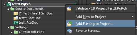
  1. Select the MACAOS.OutJob file and open
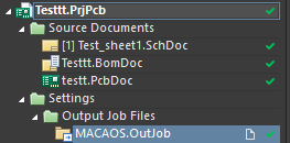
  2. The file should now be visible in project under Settings|Output Job Files

View of OutJob file in project structure

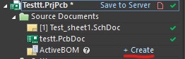
  1. If you need assembly related (Pick and Place and BOM) files, make sure that you have created an ActiveBOM file. The ActiveBom is used as the source document for the BOM.

Press create next to ActiveBOM

  1. To generate the output files: Select Folder Structure at the right and then click on Generate content.
Click "Generate Content"

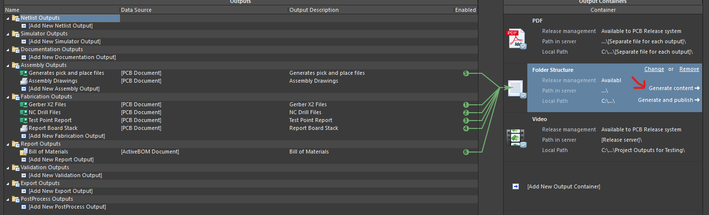
The generated files are saved to the Project outputs for [project] subfolder of the project folder.

Method 2: Create your own Output Job file

You can also create an Output Job file manually. Altium.com has a detailed guide here: Preparing Manufacturing Data with Output Jobs | Altium Designer 25 and 24 Technical Documentation

At the minimum when importing to Macaos Enterprise you need to generate:

  • Gerber files
  • Drill files

Also useful:

  • Board stack report (for reference; stackup is selected from a drop down menu in MACAOS)
  • Test point report

For assembly you also need:

  • Pick and place files: Text, metric, columns: Designator, Center-X, Center-Y, Rotation, Layer [, Comment, Footprint, etc]
  • BOM: 

If you double click on the added files listed in the OutputJob file, you can edit settings. Recommended settings for import to Macaos Enterprise:
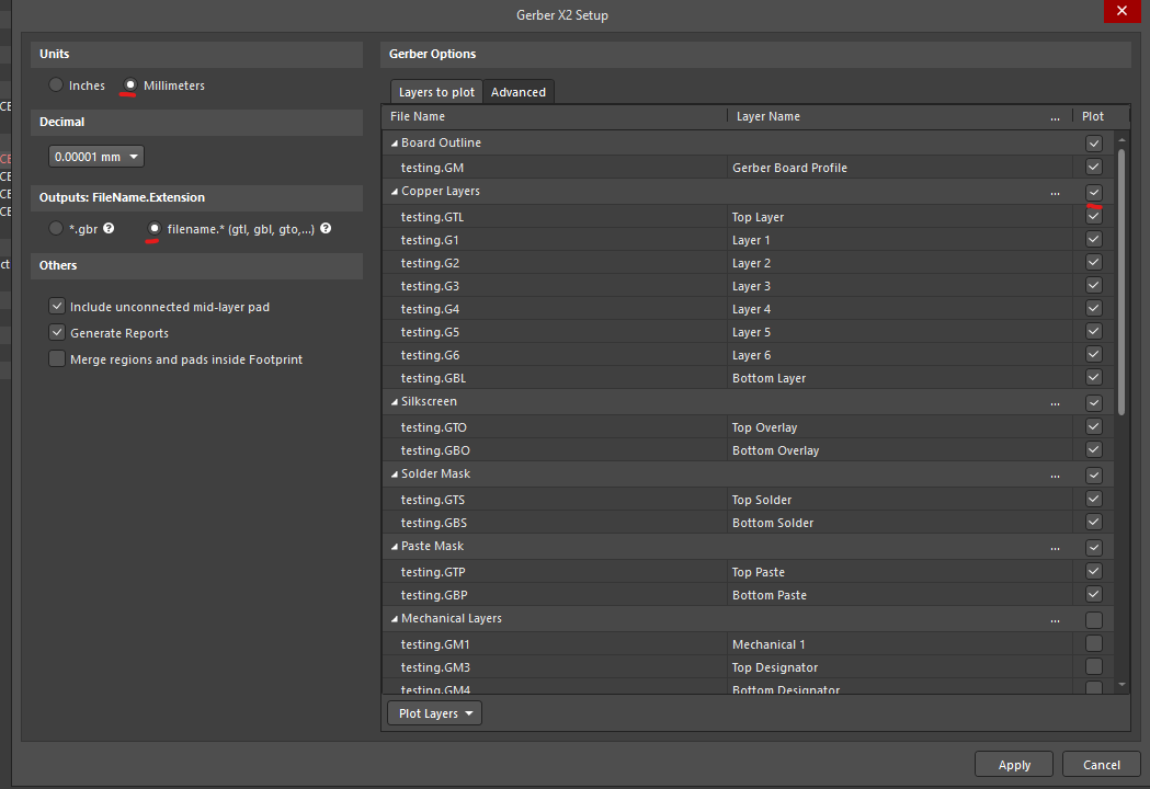
Gerber X2:

  • Choosing Gerber X2 instead of just Gerber ensures that Macaos Enterprise will automatically link your files to the correct layer
  • To avoid rounding errors, selected metric/millimeters units (rather than imperial/inches)
  • Choose the most precise decimal setting possible (most digits after decimal separator)
  • Select the option where filename extensions are corresponding to layer
  • Make sure all copper layers are selected. If you add inner layers after creating OutputJob file is created, Altium doesn't include them (by default) to gerber output.
  • Assembly layer(s) aren't included (by default) to the output, but can be good to have.
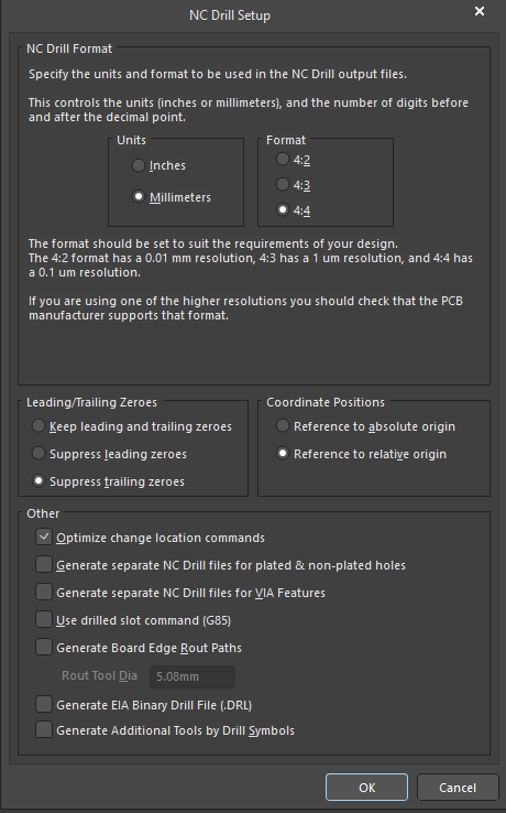
Settings for Gerber X2

NC Drill:

  • Make sure units are in millimeters
  • Make sure reference (coordinate origin) is the same as in the Gerber X2 files (usually relative origin)
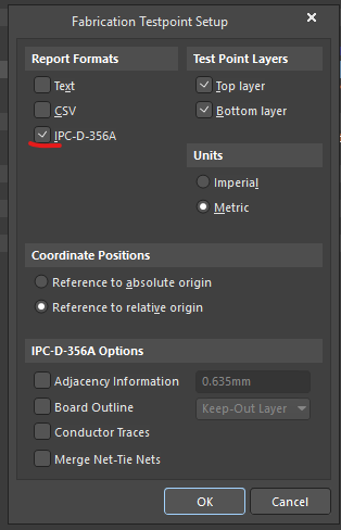
Settings for NC Drill

Test Point Report:

  • For Test Point report: select IPC-D-356A as the report format. Make sure it uses the same reference as Gerber files (usually relative origin is correct)
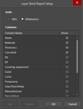
Settings for Testpoint report

Layer Stack setup:

  • Make sure units are in millimeters

Settings for Layer stack

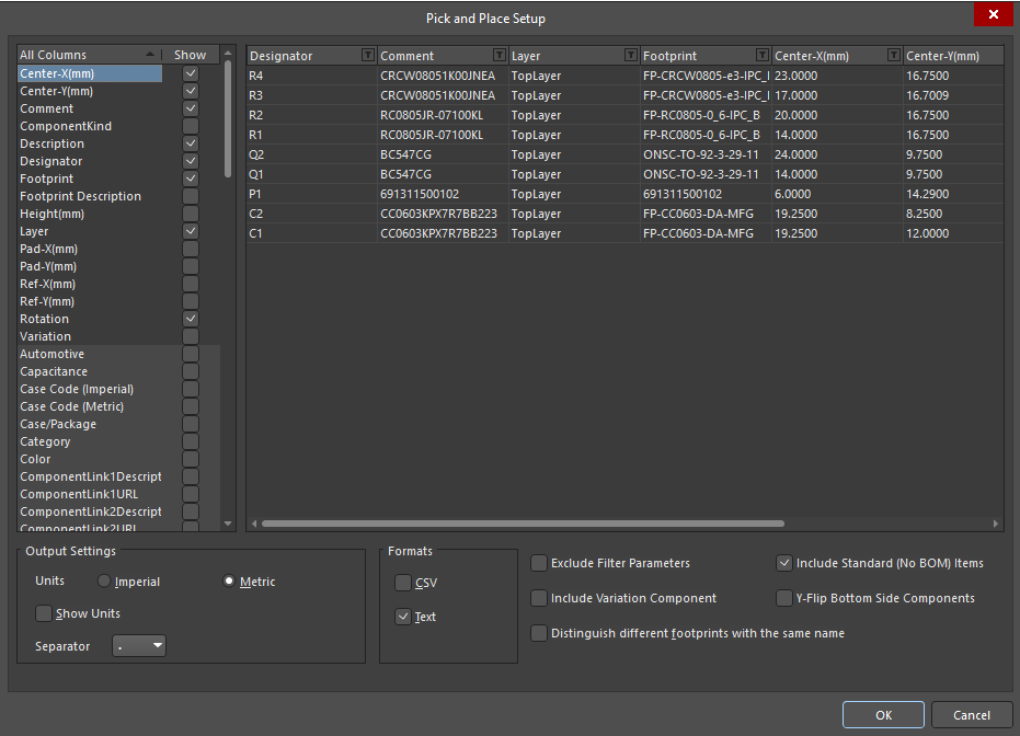
Pick and Place files:

  • Make sure units are metric, otherwise default settings should be ok
Settings for Pick and Place

BOM:

  • Make sure ActiveBOM file is added to project

Create ActiveBOM

  • Make sure you select ActiveBOM document as data source (Add New Report Output | Bill of Materials | [ActiveBOM Document]

Add new Report Output| Bill of Materials| [ActiveBOM Document]


Macaos Software AS
Sanddalsringen 5b
N-5225 Nesttun
Norway

Download gerber specification
ODB++ partner
IPC member

Footer menu

  • Contact
  • Privacy policy
Powered by Drupal

Copyright © 2025 Macaos Software AS - All rights reserved