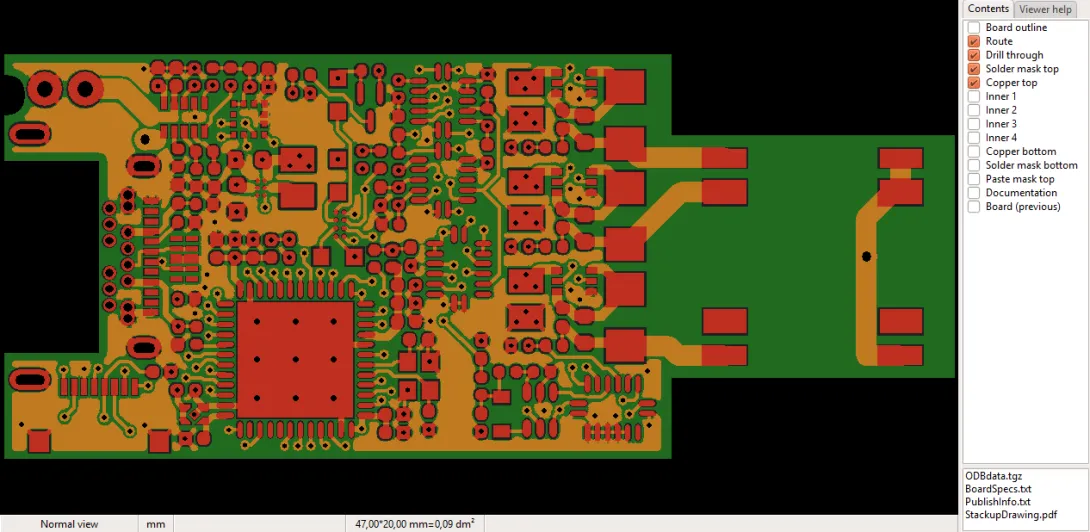
The Product viewer displays the product graphically. Note: This viewer is not used for mechanical part or off-the-shelf products.
To the right of the graphic viewer are a layer list and a file list. These are described below.
The current view mode (see below), unit of measure, cursor position and board size are displayed in a status bar at the bottom of the viewer. Click on the view mode pane or units pane to change the mode.
If you press the X key to snap the cursor to the nearest endpoint, the exact endpoint coordinates are shown. If the product contains a UL-mark, this is also shown in the status bar.
The Help tab displays a quick reference for viewer commands.
Pan and zoom
Panning and zooming can be done with the right mouse button, the mouse wheel or the keyboard.
Keyboard:
Pan: ← ↑ → ↓
Zoom to fit: Home
Zoom in: Page Up
Zoom out: Page Down
Right mouse button
Pan: click, drag horizontally or vertically until hand icon appears, then drag image as desired
Zoom to fit: click, drag upwards to left, release
Zoom in: click, drag upwards to right around area, release
Zoom out: click, drag downwards to left, release
Mouse wheel
Pan: Ctrl+rotate or Shift+rotate
Zoom in: Rotate
Zoom out: Rotate
Viewer display modes
Normally, the viewer displays all objects just as they will appear in the final product, and all objects on a layer with the same color. Three additional display modes are also available:
O Pressing the O key toggles the viewer between normal mode and centerline/outline mode. In centerline/outline mode, only the centerline of each line and arc is drawn, and only the outline of each pad and polygon is drawn. This mode is useful for seeing where objects overlap.
D Pressing the D key toggles the viewer between normal mode and highlight minimum line mode. In highlight minimum line mode, all lines and arcs with the minimum line width are highlighted.
A Pressing the A key toggles the viewer between normal mode and highlight minimum annular ring mode. In highlight minimum annular ring mode, all pads with the minimum annular ring are highlighted. Note: for boards with many holes and layers, calculating the minimum annular ring may take some time.
N Pressing the N key toggles the viewer between normal mode and highlight minimum edge to copper mode. Minimum edge to copper mode highlights the two objects having the minimum distance between an unplated edge (hole, slot or contour) and a copper object (trace, pad or copper pour.) The view also zooms in to the location of the minimum distance.
Mirrored and rotated view
To view the board as if from the bottom side, press the M key. This is useful if you want to see what the board will look like from below. Press M again to restore top-side view.
To rotate the board 90° in the viewer, press the R key. This may be useful if the board is taller than it is wide, giving a better fit to the available space in the viewer.
The current view mode is shown in the status bar at the bottom of the viewer. You can also click on this pane to change the view mode.
Measurement
When no operational mode is selected, clicking and dragging with the left mouse button displays the distance and angle from the clicked point to the mouse cursor.
Unit of measure: Press Ctrl+U or click on the units pane to toggle between inch and mm display.
Snap to endpoint: Press the X key before clicking and/or releasing the mouse button to snap the cursor to the nearest object.
An object endpoint is the start or endpoint of a line or arc, the center point of a hole or pad, or any vertex of a polygon.
Note that some CAD systems create what may appear to be a pad or polygon as a set of lines and arcs. In this case, the cursor will snap to the line or arc endpoint.
Relative origin: Press the 0 (zero) key immediately after pressing the X key to move the cursor-coordinate origin to the current mouse position. Pressing the 0 (zero) key again will reset the origin to the actual origin of the graphics content (usually the lower left corner of the board).
Exact measurements: When making measurements, you can use the X key to snap the cursor to the nearest object endpoint and make an exact measurement. The procedure is as follows:
- Move the cursor near the object endpoint where you wish to start measuring.
- Press the X key and the cursor will move to the endpoint. Release the X key.
- Click the left mouse button to begin measuring.
- While holding the mouse button down, move the cursor near the object endpoint to which you wish to measure.
- Press the X key and the cursor will move to the endpoint. Release the X key.
Lock cursor: Prese Alt+X or Alt+Y to lock the cursor to the current X or Y position. Press Esc to release the lock.
Cursor position: Pressing the Y key opens the Cursor position dialog box, which allows the cursor position and/or relative origin to be specified directly.
The X and Y edit boxes specify the new cursor position relative to the point specified by the Position method radio buttons. The Buttons increment radio buttons specify how far the cursor will move when using the arrow buttons of the X or Y edit boxes.
The Lock cursor check boxes lock the cursor (as with Alt+X or Alt+Y) after pressing OK.
Note: The mouse wheel may be used to zoom or pan while the cursor position dialog is open.
Padstack details
Press the Ctrl and Alt keys and click on a drill hole to view the shapes and sizes of all pads in the padstack.
Note: Only pads whose center is the same as the center of the hole are included in the padstack report.
Layer list
The check boxes in the layer list control which layers are visible.
Right-click in the layer list to quickly show or toggle layer visibility for specific layers.
Right-click on a layer name to change the display color for that layer. The new color will be used in all program modules.
File list
A list of files attached to the product. These are typically documentation files for the product.
- Viewing files: Double-click on a filename to view the file. The file will open in the associated application for that filetype (in the same manner as for the operating system).
- Saving files: Right-click on a filename and choose Save as... to save the file locally.
- Adding files: Right-click on the list and choose Add file... to add a new file to the product.


