Note: This module is only available in Macaos Enterprise for Engineers and Macaos Gallery.
The Import Module converts output data from an Electronic CAD system to a Macaos Enterprise product. In most cases, you will be importing a set of Gerber and Drill files, or ODB++ data. Each of these files must be linked to the correct layer of the PCB. It is also necessary to specify the desired layer buildup for the product, and perhaps some other properties as well.
See our guidelines for how best to export your Gerber and Drill files from your CAD system.
Note: In an ODB++ dataset, the graphic data is already linked to specific layers. This layer linking should be checked (and corrected, if necessary) before specifying product properties.
You can also add fiducial marks and other symbols to the product prior to publishing. There are also tools for inspecting and measuring features of the product.
Once a product has been completely specified, you must publish (Macaos Enterprise) or save (Macaos Gallery) the product so that it will be available for purchase (Macaos Enterprise), panelization, creating a solder paste stencil or in-circuit test fixture, working with assembly data, etc.
A complete data set streamlines production
- Gerber and Drill files: At the minimum, you need a Gerber file for each layer of the PCB. In addition, you should have a Gerber file containing the board outline (as well as the outlines of cutouts and centerlines of slots, if any). If the board has drilled holes, then there must be one or more drill files (in either NC Drill or Gerber format).
- Gerber Job file: A Gerber Job file will speed the import of your data. The Gerber Job file specifies which layer each of the Gerber/Drill files represents. It may also include additional board specifications, such as layer buildup and mask colors.
- ODB++ data: Alternatively, ODB++ data may be imported. This would replace the Gerber, Drill and Gerber Job files.
- Pick and place data: PnP data includes the designator, location and rotation of each component on the PCBA. It is helpful if the PnP data also includes fiducial marks and test points (for in-circuit testing). Macaos Enterprise for Engineers stores this information on the Component Top and Component Bottom layers of the PCB.
- Bill of materials data: BOM data includes the designator, manufacturer part number, manufacturer and other properties of each component on the PCBA. Macaos Enterprise for Engineers stores this information on the Component Top and Component Bottom layers of the PCB, using the designator to link components from the BOM data to components from the PnP data.
- IPC-D-356 data: An IPC-D-356 file contains data used for bare-board testing. This file is very useful for the PCB manufacturer. In addition, Macaos Enterprise for Engineers uses this data to determine key pins and component outlines (in the Assembly Data Manager), to link stencil openings to components (when designing a solder paste stencil), and to annotate test pins (when designing test fixtures).
When all of this data is present, the various modules in Macaos Enterprise for Engineers will do most of the work for you.
Module overview
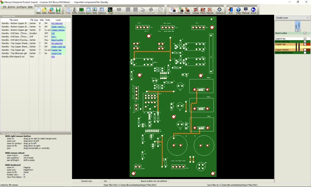
The Import Module window consists of three main elements:
- an icon bar (top)
- a product data and specifications region (left)
- a graphic display region with layer list (right)
There are six “panes” of information in the specifications region:
- The Files pane lists files in the project and each file’s associated layer (if any).
- Use the Drill files and tools pane to inspect and modify the drill holes in the product.
- Use the Board outline pane to define the board's outer contour, as well as cutouts or scoring lines.
- Use the Specs pane to specify the stackup, finish, colors and other properties.
- Use the Stats pane to specify minimum feature sizes. This pane also displays several other product parameters.
- Use the ID & Options pane to specify product identification and specify product options.
You can also carry out graphic actions before saving your imported data, including:
- Use Align drill when your drill files do not have the same origin as your Gerber files.
- Use Padstack report to inspect the diameters of pads around a hole.
- Use Fiducial marks to place fiducial marks on the board.
- Use Batch no. to specify where the manufacturer should place their product/batch number.
- Use Symbols to place text, bar codes or a variety of graphic symbols on the board.
- Use Remarks to attach a manufacturing remark to a specific position of the board.
- Use Align Components when your component data does not have the same origin as your Gerber files. This function is accessed by clicking on the small down-arrow of the Align drill button.


