Skip to main content Skip to footer
Home
User manuals

Main navigation

  • Home
  • Enterprise for Engineers
    • Program overview
      • Getting started
      • Product browser
      • Recent activity
      • Viewer tab
        • Product viewer
      • Specifications tab
        • Product Specifications viewer
        • Product documentation
        • Product buildup viewer
        • PCBA Components
        • Product sharing
      • Quotation
      • History
      • Shopping Cart
    • File menu
    • Show menu
      • Find product
      • View mode
    • Products menu
    • Operations menu
      • Import PCB
      • Panelize PCB
      • Create Stencil
      • Add Masks to PCB
      • Assembly Data Manager
      • Solder Pallet Designer
      • Depanelize PCB
      • Test Fixture
      • Test Fixture (legacy)
      • Connector chooser
      • Import 3D Mechanical Part
      • Order History
    • Configuration menu
      • Partner manager
      • User details
      • User manager
      • Options
      • Move ME to new PC
    • What's new
    • Release notes
  • Enterprise for Purchasers
    • Activity Overview
    • Product details
    • Search for product
    • Additional Operations
      • Partner manager
      • User profile
      • User manager
      • Options
  • Macaos Gallery
    • Product Browser
      • Product Explorer
      • Simple PCB Editor
      • Exporting product data to Gerber
      • Searching for products
      • MIF File history
      • Icon bar
      • Product info
    • Operations
      • Standard operations
        • Import PCB
        • Panelize PCB
        • Create Stencil
        • Add Masks to PCB
      • EMS version operations
        • Assembly Data Manager
        • Solder Pallet Designer
        • Depanelize PCB
        • Test Fixture
    • Technical Documentation
    • Configuration
    • Gallery PreCAM
      • Configuration options
      • Quotation module
        • Quotations
        • Calculated prices
        • Adjusting prices
        • Quotation
      • Quotation archive
        • Folders
      • Price Editor module
      • Price list editor
        • Price element editor
        • Selector editor
        • Curve editor
        • Price list wizard
      • Sales office settings
      • Holidays
      • About prices
        • Factory price
        • Retail price
        • How is a price calculated?
      • Reference
        • Price list
        • Price element
        • Curve function
        • Parameters
      • Example: Creating the Demo price list
        • Using the price list wizard
        • Refining the price list
        • Retail price
    • What's new
    • Release notes
  • Subsystem Manuals
    • Product editor Modules
      • Assembly Data Manager (ADM)
      • Assembly Masks
      • Depanelization
      • Import PCB
      • Mechanical Parts
      • Panelization
      • Solder Pallet
      • Solder Paste Stencils
      • SPRINT Test Fixtures
      • Test Fixtures (Legacy)
    • Product display modules
      • PCBA Components
      • Product Buildup Viewer
      • Product History
      • Product Specifications Viewer
      • Product Viewer
    • Other Modules
      • Connector Chooser
      • Order History
      • Partner Manager
      • Product sharing
      • Quotation
      • Search
      • Shopping Cart
      • User Details
      • User Manager
  • Additional info
    • Release notes
      • What's new in ME for Engineers
      • What's new in ME for Purchasers
      • What's new in Gallery
      • What's new in Convergence
      • ME for Engineers release notes
      • ME for Purchasers release notes
      • Gallery release notes
      • Convergence release notes
      • Perception release notes
    • Gerber file generation tips
      • Using KiCad
      • Using Eagle
      • Using CADint
      • From other systems
    • Performance Classes
    • Solder paste stencil ratios
    • Surface finishes
    • Via types
    • Panelization scripts
  • Contact
  • Back to Macaos website

Text and bar codes

Breadcrumb

  • Home
  • Panelization
  • Text and bar codes

Text propertiesYou may add text, bar codes or annotation fields to the panel frame.

Plain text on the legend layer may also be placed within individual boards, which is useful when giving the boards in the panel individual position identifiers.

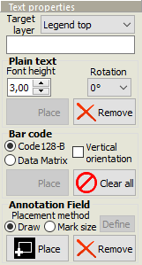
Select a target layer, and enter the text to place.

Plain text

The Font height specifies the height of the characters. Select a Rotation, if desired. Text on a bottom layer will automatically be mirrored.

Click on the Place button (so that it is “down”) and then click where you wish to place the text. Text may only be placed where it will fit within the frame of the panel (or, on Legend layers, within the board).

To remove text, click on the Remove button (so that it is “down”) and then click on the text to remove.

Bar code

A bar code may be placed on either legend layer of the panel frame. The bar code is generated in either Code128-B or Data Matrix ECC 200 format.

White legend on green solder mask will give an inverse bar code image. Note: Many bar code reader apps do not support inverse images. We recommend the “ScanLife” app by Scanbuy, Inc., available at www.getscanlife.com.

If a Code 128-B bar code is to be placed along one of the vertical edges of the frame, then check Vertical orientation. A bar code on the bottom layer will automatically be mirrored.

Click on the Place button (so that it is “down”). Then click where you wish to place the bar code. A bar code may only be placed where it will fit within the frame of the panel. It is not possible to place a bar code on the boards.

To remove bar codes, click on the Clear all button. All bar codes will be removed.

Note: The bar codes are limited to ASCII characters from 32 to 127. This includes all digits, all letters in the English alphabet, and many symbols. Non-English characters or characters with accents or other diacritical marks are not supported.

Annotation field sizeAnnotation field

An annotation field is a solid rectangle which may be used for laser etching, handwritten serial numbers or other information. It may be placed on a legend or solder mask layer of the panel frame.

Note: If you need to place an annotation field within the boards of the panel, this can be done with the Assembly masks design action.

Click on the desired layer name in the layer list, and then click on the Place button (so that it is “down”). Choose whether the annotation field is to be drawn or placed with a defined mark size.

If drawn, then draw a rectangle defining the size of the annotation field.

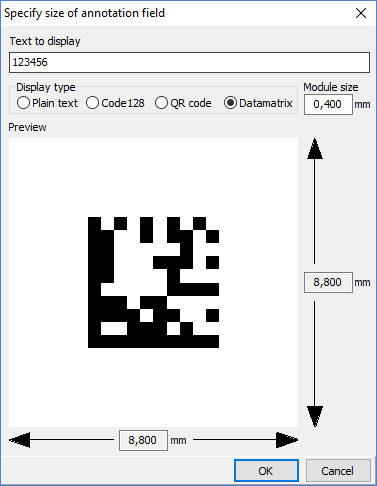
If placed with a defined mark size, click first on the Define button. This opens a dialog box for calculating the appropriate size for a text or bar code. You should enter a text similar (and with the same number of characters) as will be actually used. After closing the dialog box, place the annotation field as desired.

Note: For laser engraved 2-dimensional bar codes, we recommend a module size of 0.5 mm or larger.

Note: Two-dimensional bar codes use different encodings for a text with numbers-only, English alphanumeric text, or containing other-language characters. The actual bar code may differ in size from the sample displayed in the dialog if the sample text differs in number of character types.

To remove annotation fields, click on the Remove button (so that it is “down”) and then click on the fields to remove.

Book traversal links for Text and bar codes

  • ‹ Frame holes
  • Up
  • Bad marks ›

Macaos Software AS
Sanddalsringen 5b
N-5225 Nesttun
Norway

Download gerber specification
ODB++ partner
IPC member

Footer menu

  • Contact
  • Privacy policy
Powered by Drupal

Copyright © 2025 Macaos Software AS - All rights reserved