Skip to main content Skip to footer
Home
User manuals

Main navigation

  • Home
  • Enterprise for Engineers
    • Program overview
      • Getting started
      • Product browser
      • Recent activity
      • Viewer tab
        • Product viewer
      • Specifications tab
        • Product Specifications viewer
        • Product documentation
        • Product buildup viewer
        • PCBA Components
        • Product sharing
      • Quotation
      • History
      • Shopping Cart
    • File menu
    • Show menu
      • Find product
      • View mode
    • Products menu
    • Operations menu
      • Import PCB
      • Panelize PCB
      • Create Stencil
      • Add Masks to PCB
      • Assembly Data Manager
      • Solder Pallet Designer
      • Depanelize PCB
      • Test Fixture
      • Test Fixture (legacy)
      • Connector chooser
      • Import 3D Mechanical Part
      • Order History
    • Configuration menu
      • Partner manager
      • User details
      • User manager
      • Options
      • Move ME to new PC
    • What's new
    • Release notes
  • Enterprise for Purchasers
    • Activity Overview
    • Product details
    • Search for product
    • Additional Operations
      • Partner manager
      • User profile
      • User manager
      • Options
  • Macaos Gallery
    • Product Browser
      • Product Explorer
      • Simple PCB Editor
      • Exporting product data to Gerber
      • Searching for products
      • MIF File history
      • Icon bar
      • Product info
    • Operations
      • Standard operations
        • Import PCB
        • Panelize PCB
        • Create Stencil
        • Add Masks to PCB
      • EMS version operations
        • Assembly Data Manager
        • Solder Pallet Designer
        • Depanelize PCB
        • Test Fixture
    • Technical Documentation
    • Configuration
    • Gallery PreCAM
      • Configuration options
      • Quotation module
        • Quotations
        • Calculated prices
        • Adjusting prices
        • Quotation
      • Quotation archive
        • Folders
      • Price Editor module
      • Price list editor
        • Price element editor
        • Selector editor
        • Curve editor
        • Price list wizard
      • Sales office settings
      • Holidays
      • About prices
        • Factory price
        • Retail price
        • How is a price calculated?
      • Reference
        • Price list
        • Price element
        • Curve function
        • Parameters
      • Example: Creating the Demo price list
        • Using the price list wizard
        • Refining the price list
        • Retail price
    • What's new
    • Release notes
  • Subsystem Manuals
    • Product editor Modules
      • Assembly Data Manager (ADM)
      • Assembly Masks
      • Depanelization
      • Import PCB
      • Mechanical Parts
      • Panelization
      • Solder Pallet
      • Solder Paste Stencils
      • SPRINT Test Fixtures
      • Test Fixtures (Legacy)
    • Product display modules
      • PCBA Components
      • Product Buildup Viewer
      • Product History
      • Product Specifications Viewer
      • Product Viewer
    • Other Modules
      • Connector Chooser
      • Order History
      • Partner Manager
      • Product sharing
      • Quotation
      • Search
      • Shopping Cart
      • User Details
      • User Manager
  • Additional info
    • Release notes
      • What's new in ME for Engineers
      • What's new in ME for Purchasers
      • What's new in Gallery
      • What's new in Convergence
      • ME for Engineers release notes
      • ME for Purchasers release notes
      • Gallery release notes
      • Convergence release notes
      • Perception release notes
    • Gerber file generation tips
      • Using KiCad
      • Using Eagle
      • Using CADint
      • From other systems
    • Performance Classes
    • Solder paste stencil ratios
    • Surface finishes
    • Via types
    • Panelization scripts
  • Contact
  • Back to Macaos website

Break-off tabs

The Panelization module supports two kinds of break-off tabs. Edge tabs are tabs placed along the edge of a board. Corner tabs are placed at the corner of a board.

Edge tabs may be removed by breaking, cutting or milling the tab. Milling is the safest method for removing tabs. Breaking or cutting a tab may lead to damaged solder joints, especially on surface mounted components near the break-off tab. When a corner tab is placed at the corner of all adjacent boards (i.e. not along the edge of a neighboring board) then it can be removed by drilling rather than by cutting the tab. See the Depanelization module manual for more info.

Break-off tab properties
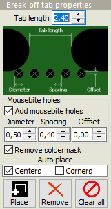
Tab length: This value specifies the length of the tabs. For edge tabs, this is the length of the narrowest point on the tab. For corner tabs, the width of the narrowest point is about 40% of the specified tab length.

Holes: A row of “mousebite” holes may be added to tabs. Diameter, spacing and offset of the holes may be specified. The number of holes is determined automatically. Mousebite holes are not added to corner tabs.

Remove soldermask: If checked, solder mask will be removed from around each break-off tab and its mousebite holes (if any). This helps prevent cracks in the solder mask when cutting the tabs. Note: Removing the solder mask may expose copper near tabs. Check all tabs carefully.

Autoplace: This function places tabs at the midpoints or corners of each board's outer contour. For boards with curved edges, the endpoints of arcs are treated as corners.

For boards with complex contours and for multi-product panels, autoplacement may give undesirable results.

Manual placement: To place tabs manually, click on the Place button (so that it is “down”).

When you click and drag the mouse pointer, a horizontal or vertical line appears. When you release the mouse button, tabs will be placed at each point where the line crosses a board edge.

Alternatively, tabs can be placed one at a time. Clicking on the edge of a board will place tabs at that position on each instance of that board in the panel. To place a tab on only one board, hold the Ctrl key down while clicking to place the tab.

For wave soldered panels, you should add at least one break-off tab to inner contours so that the material will not be removed during production.

Tab removal: To remove all tabs, click on the Clear all button.

To remove individual tabs, click on the Remove button (so that it is “down”). Left-click and draw a selection rectangle around the tab(s) to remove. All tabs at that position on all boards in the array will be removed. To remove a tab from only one board, hold the Ctrl key down while removing the tab.

Note: If a multi-product panel is specified without any tabs, the boards within the panel will be delivered as individual boards rather than as a panel. (A single-product panel may not be specified without tabs.)

Book traversal links for Break-off tabs

  • ‹ Panel properties
  • Up
  • Fiducial marks ›

Macaos Software AS
Sanddalsringen 5b
N-5225 Nesttun
Norway

Download gerber specification
ODB++ partner
IPC member

Footer menu

  • Contact
  • Privacy policy
Powered by Drupal

Copyright © 2025 Macaos Software AS - All rights reserved