Note: Basic Gerber files are deprecated. The "Standard Gerber" (RS-274D) format was revoked by the format owner in 2014. If you are using a CAD system which only generates Basic Gerber files, then we strongly recommend that you acquire a more modern system.
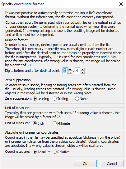 Basic Gerber files contain only x-y coordinates and device codes. In order for these files to be interpreted, there are a number of parameters which must be defined externally to the coordinate file. When importing a Basic Gerber file, the Specify coordinate format dialog box must be filled out so that the file can be interpretated correctly. There are four parameters which must be specified. Usually, these settings can be determined from the Gerber Export settings of the CAD program which generated the files.
If you are unable to determine the correct parameters, then you should try the default values and check carefully that the resulting image has the correct size and shape. The Specify coordinate format dialog box explains the meaning and consequences of each parameter in greater detail.
Once the coordinate format has been specified, it will be used for any additional Gerber files that are imported; until the File|New Product command is executed or the Import Module is closed.
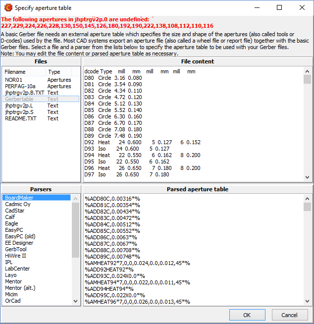 Basic Gerber files also need an Aperture Table, which lists the sizes and shapes of the “Apertures” (or drawing shapes) referred to by the device codes in the coordinate file. Sometimes, Basic Gerber files are generated in accordance with a standardized table, such as NOR01 or PERFAG-10a, but most CAD systems generate a separate aperture file (or wheel file or tool report) together with the Basic Gerber files.
If undefined apertures are encountered while importing a Basic Gerber file, the Specify aperture table dialog box opens. This dialog box lists the undefined device codes (apertures) which were found in the coordinate file. The upper left region lists standardized aperture tables as well as all non-image files listed in the Files pane. Clicking one one of these files causes the file contents to be displayed in the upper right region.
Nearly every CAD system generates aperture files differently. Once you have located the correct aperture file, you should choose the parser for your CAD system from the list in the lower left region. The parsed aperture table will then be shown in the lower right region. Once an aperture table is located that defines all of the undefined apertures listed at the top of the dialog box, the OK button is enabled.
Note: It is sometimes possible to come up with a valid aperture table even though the wrong aperture file or the wrong parser is used. If you are unsure of the aperture table, you should inspect the graphic display carefully to insure that the Basic Gerber files have been interpreted properly.
If the coordinate format or aperture table was not correctly specified, choose File|New Product and repeat the import process with the correct parameters.


