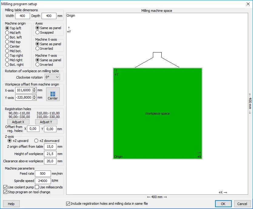
The Milling program setup dialog box specifies the transformation of coordinates from the workpiece coordinate system to the coordinate system of the milling machine. These include machine specific coordinate parameters, placement of the workpiece within the machine space, registrations holes (if applicable), z-axis parameters, and additional machine parameters.
Machine specific coordinate parameters
Machine table dimensions: The width and depth of the milling table. These values are used to display the milling space in the dialog box, and to center the workpiece within the milling space.
Machine space origin: The location of the coordinate origin in the machine space. Top is farthest from you when facing the machine.
Axes: Normally, the machine axes will be the same as the (unrotated) workpiece, i.e. X is X and Y is Y, or X is left-right and Y is front-back. If necessary, they may be swapped.
Machine X-axis and Machine Y-axis: Normally, the positive direction of a machine axis is the same as for the workpiece. If necessary, the direction may be inverted.
Placement of the workpiece within the machine space
Rotation of workpiece on milling table: The placement of the workpiece on the table may be rotated, if desired. This rotation is added to any rotation of the workpiece that may have been specified in the designer module.
Workpiece offset from machine origin: This is the offset from the machine space origin to the workpiece origin. This may be adjusted as necessary to place the workpiece at the desired location on the milling table.
The Center button sets the workpiece offset so that the workpiece is centered on the table. This is useful after having made changes to the machine specific coordinate parameters which may have moved the fixture outside of the milling space.
Registration holes
If the workpiece has registration holes (e.g. for a depanelization fixture), then the coordinates of the four registration holes are displayed. If desired, the Adjust X and Adjust Y buttons may be used to adjust the offset so that the coordinates of the registration holes are a multiple of 10.0 mm.
Offset from reg. holes: If (due to manufacturing tolerances) the location of the registration holes in the workpiece is incorrect, it may be desirable to add a small offset to the milling program.
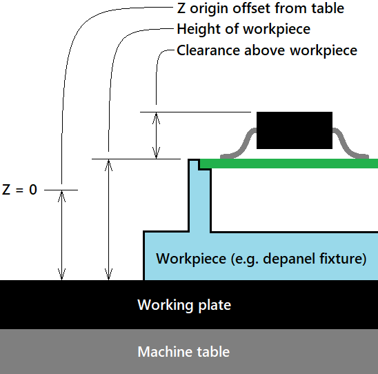 Z-axis parameters
Z-axis: The Z-axis is normally positive in the upward direction. If necessary, this may be inverted.
Z-origin offset from table: This is the distance from the bottom edge of the workpiece to the Z-axis origin. If the origin is above the workpiece bottom, and +Z is upward, then this will be a positive value. If you make use of a tool homing device to set the Z-axis origin, then this offset should be equal to the thickness of the homing device when it rests on the same surface as the workpiece.
Height of workpiece: This is the distance from the bottom edge of the workpiece to the top of the workpiece. By default, this offset is automatically calculated from the workpiece dimensions. However, it may be adjusted, if necessary.
Clearance above workpiece: This should be slightly larger than the maximum height of any objects extending from the upper surface of the workpiece (e.g. components on the upper side of a panel being depanelized). The cutting tool will retract to 1mm above this height before moving from one cutting point to the next.
Additional machine parameters
Feed rate: The speed at which the cutting tool travels through the material being cut.
Spindle speed: The clockwise rotation speed of the cutting tool. Note: Counterclockwise spindle rotation is not supported.
Use coolant pump: If checked, the program will turn on/off the machine’s coolant pump.
Use milliseconds: If checked, the machine expects the spindle spin-up delay to be specified in milliseconds. Otherwise it is specified in seconds.
Combined or separate files
When generating milling data for multiple output processes (such as for both sides of a solder pallet), the data may be output as a combined file or as two separate files. Use the Include… check box to specify whether one or two output files will be generated.
Machine specific parameters
Upon closing the dialog box, machine specific parameters are saved for re-use the next time a milling program is generated. These include: machine table width, depth and origin, axis swapping and inversion, z-axis inversion, feed rate, spindle speed, coolant, and time in seconds or milliseconds. The option to include/exclude registration holes in the milling file is also saved.


