 The Panel design action is used to specify the quantity and spacing of board instances on the panel. Use the Panelize button to create the panel, and the Unpanelize button to “undo” the panel.
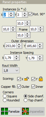
Instances (x * y): These values specify the number of boards in the X and Y directions, respectively. The total number of boards in the array is the product of the X and Y values.
Rot. 90°: If checked, the board instances will be rotated 90 degrees within the panel.
Frame: These values specify the width of the panel frame on each edge of the panel. These values are specified in millimeters.
Outer dimensions: These values show the total width and height of the panel frame. Modifying an outer dimension will automatically change the corresponding frame widths.
Instance Spacing: These values specify the distance between each instance in the array. Instance spacing may not be less than the rout width. Be sure to specify an adequate instance spacing, if you will be adding bad marks to the panel.
Rout width: This value specifies the diameter of the routing tool used to cut the slots between the boards. Use the default value (1.6mm) unless you have a specific need for a different value (such as due to thin slots or a small inner corner radius).
Scoring: If checked, scoring (V-cut) will be used between boards rather than routing along the outer X and/or Y edges.
Mixed scoring and routing
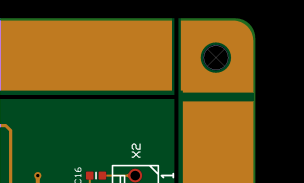
 When scoring is used with non-rectangular boards, only the edges which follow the bounding rectangle will be scored. All other edges will be routed (milled). This can lead to small burrs or pointed corners at the junction between routing and scoring.
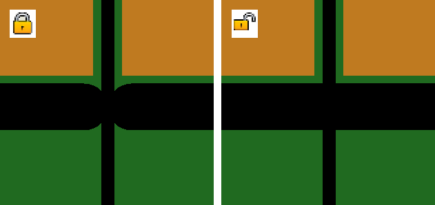
By default, the routed slots are “locked” to stop at the scoring line, so that they will not damage neighboring boards. Slots that will cross the scoring line into waste material will do so in most cases. However the results may be unsatisfactory for slots that are not straight lines or that cross the scoring line with a small angle.
This behavior may be “unlocked,” by clicking on the padlock icon. When scoring is unlocked, the routed slots will extend at least one radius beyond the scoring line, without protecting neighboring boards.
Care should be taken when using unlocked scoring. Unlocked scoring is most suitable for symmetrical boards. In other cases, there is a risk of unwanted notches in neighboring boards.
Alternatively, you may increase the Instance spacing to be at least as large as the Rout width. This will create double scoring lines, thereby allowing the routing slots to extend beyond the scoring lines without damaging neighboring boards.
 Scoring lines in the panel frame
Scoring lines extend normally from one edge of a panel to the opposite edge. Individual scoring lines may be pulled back from the outside panel edge to the inside edge of the panel frame by holding the mouse pointer over the end of the scoring line and pressing Ctrl+V. Note: The actual scoring cut will extend a few millimeters beyond the end of the displayed scoring line, due to the diameter of the scoring saw blade. Note: Manufacturing a panel with this feature requires Jump Scoring. Not all manufacturers are able to deliver panels with Jump Scoring.
Rotating or flipping a board in a panel with scoring
It is not normally possible to select, move or rotate individual boards when scoring has been chosen. However, a board may be rotated 180° (by pressing the Space key) or flipped (by pressing Shift+Space) while the mouse pointer is within the board to be rotated/flipped.
Copper fill: The frame may be filled with copper on the outer and/or inner layer(s). Outer layers are filled with solid copper. Inner layers are filled with a pattern of 5mm diameter dots. Note: Adding copper to the outer layer increases panel stiffness, but may affect soldering temperature.
Copper fill helps increase the panel stiffness during the soldering process, and is especially useful for lead-free soldering. However, copper fill is not advised for vapor-phase soldering since the large copper mass may steal too much heat.
Corners: Choose between square, rounded or chamfered corners on the panel frame. Chamfered corners may be chosen for either top feeding or side feeding. Note: Rounded or chamfered corners are not available if the panel frame width is too small for the corner modification.


