Curve editor
The curve editor is used to create and/or modify a curve price element’s curve function.
Typically a curve is created or modified by making copying and/or comparing with a reference curve. By default, the price element’s original curve is the reference curve. However, any existing curve may be chosen as a reference curve.
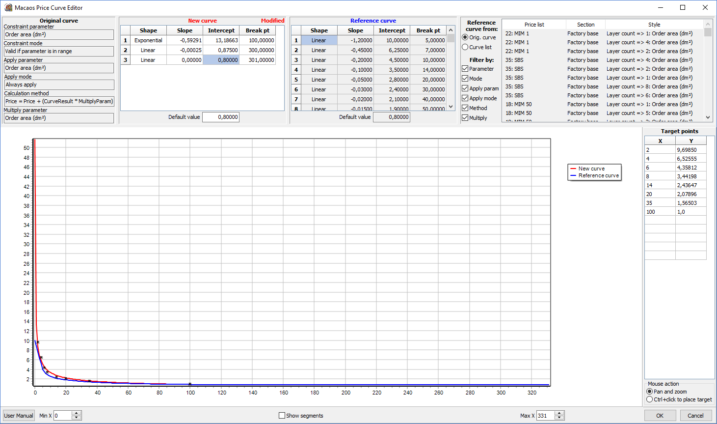
The upper region of the curve editor has four panes:
- The Original curve pane lists the properties of the curve price element being edited
- The New curve pane lists the segments and default value of the editable curve
- The Reference curve pane lists the segments and default value of the reference curve
- The Curve list pane is used to select a reference curve
The lower region has a Curve viewer to display both the new curve and the reference curve graphically. In addition, a set of target points may be specified, to aid in specifying the new curve.
Initially, the reference curve is the price element’s original curve. If desired, a different reference curve may be selected from the curve list. The curve list may be filtered to only show curves whose properties match the properties of the original curve, as determined by the Filter by check boxes.
A new curve may be created by copying an existing curve, by generating a curve from target points or by manually entering the values for each curve segment as well as the curve’s default value.
- To copy the reference curve, right click on the New curve grid and choose Copy reference curve.
- To create a curve from target points, right-click on the Target points grid and choose one of the Add segment operations. (See the Target points section for more details.)
- To manually enter curve segment values, right click on the New curve grid and choose Add segment to add a row to the grid, or Delete segment to remove the selected row from the grid. The values for each segment may be modified by entering the new values directly I the grid. (Note: The shape is chosen by selecting Linear or Exponential from a drop-down list.)
The new curve may be reset to its original specifications by right clicking on the New curve grid and choosing Restore original curve.
Curve viewer
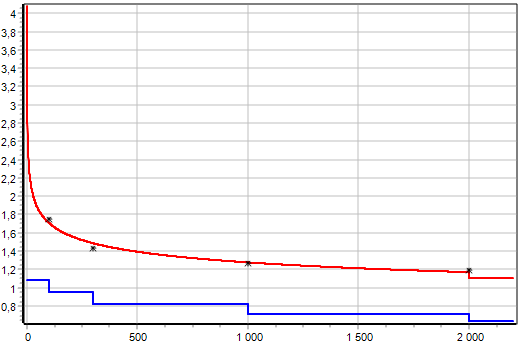
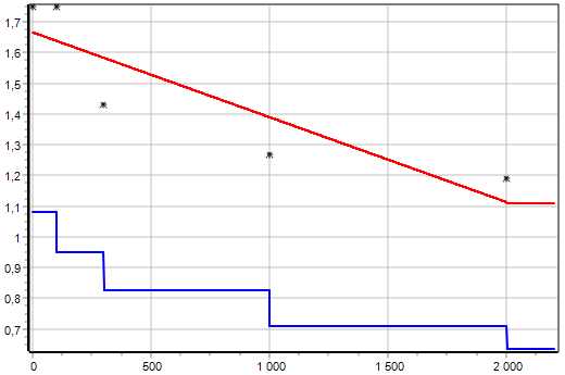
The curve viewer displays both the new curve (red) and the existing curve (blue). The Min X and Max X values may be used to specify the range of the graph’s X-axis. The Y-axis automatically scales to display all curve values within the X-axis range.
To zoom in, left-click at the lower left corner of the desired zoom area, and while holding the mouse button drag the mouse to the upper right corner of the zoom area before releasing the button.
To zoom to fit, left-click and drag the mouse button toward the left, then release the mouse button.
To pan, right-click and move the mouse, then release the mouse button.
Note: Pan and zoom is only enabled if the Pan and zoom mouse action has been selected.
Each segment of a curve applies from the end of the previous segment to the segment's break point. It may be desirable to set the break point to the x-value where the two segments cross. To see this, set a check mark for Show segments and then zoom in to the area where the segments cross.
Target points
Finding the right parameters, especially for exponential segments, may take some trial and error. To aid in this process, target points may be added to the graph. Target points are shown as black stars.
Target points may be created in several manners:
- First select the Ctrl+click to place target mouse action, then press the Ctrl key and click at the desired location in the curve viewer to add a target point to the grid.
- Enter the x and y values directly into the Target points grid. If necessary, right-click on the grid and choose Insert row. Note: X values must be integer values.
- Right-click on the Target points grid and choose Paste to load target points from the clipboard. The clipboard should contain two columns of values from an external spreadsheet. Note: This operation deletes all existing target points.
- Right-click on the Target points grid and choose Load from reference curve or Load from new curve to load target points from the chosen curve. Note: This operation deletes all existing target points.
Target points are automatically sorted in the grid in order of increasing x value.
To delete a target point, select the desired row in the Target points grid, then right-click and choose Delete row. To delete all target points, right-click and choose Clear all.
One or more curve segments may automatically be generated from target points by right-clicking on the Target points grid and choosing the desired Add segment operation. Note: Each of these operations deletes any segments from the new curve whose break point is within the range of the target point x values before creating the new segment(s).
- Stairstep: This operation creates a constant (zero-slope) linear segment for each target point. The x value of the target point is used as the segment’s break point, and the y value is the intercept. Note: Target points with an x value less than 2 are ignored.
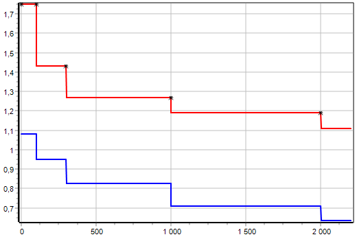
- Point to point: This operation creates a linear segment from each target point to the next target point.
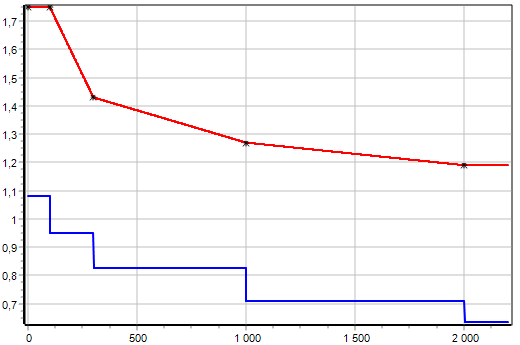
- Linear best fit: This operation creates a single linear segment which is a least-squares best fit of all target points.
- Exponential best fit: This operation creates a single exponential segment which is a least-squares best fit of all target points. Note: Target points with an x value less than 1 are ignored.